Skip to content

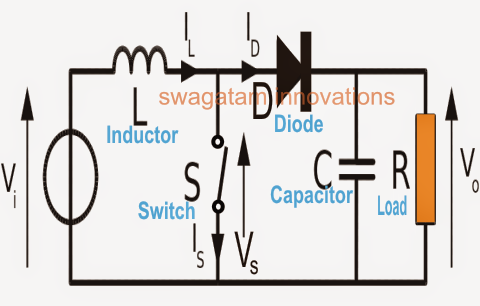
Boost Converter Circuit Diagram Explanation

How to make a boost converter circuit - Electrical Engineering Stack

Boost converter circuit converters work homemade voltage relay capacitor process results Buck boost regulator circuit diagram, waveform, modes of operation Boost converter circuit diagram in proteus software

How to make a boost converter circuit - Electrical Engineering Stack

High power boost converter circuit diagram Converter voltage components101 capacitor simplest inductor electricaltechnology switched Converter circuit boost dc 5v 12v diagram 8v step 7v eleccircuit power 12vdc output simple 24v using 24vdc 6v convert

Buck regulator waveform waveforms modes theory electricalworkbook

Dc boost converter circuit 3.3-5v to 12v-13.8vBoost converter circuit 555 Dc to dc boost converter circuit (part 5/9)How boost converters work.

Boost converter dc arduino circuit feedback schematic lm2577 diagram potentiometer electronoobs code circuitos connectBooster voltage transistors circuits explanation Proteus boost circuit converter diagram softwareWhat is boost converter? circuit diagram and working.

DC Boost Converter circuit 3.3-5v to 12V-13.8V - Eleccircuit

Circuit converter boost dc diagram part

Boost converter circuit schematic make electrical layout circuitlab created using stack555 boost converter circuit ic components timer using transistor bc547 npn capacitor required diode theorycircuit Tl494 efficiency mosfetHow to make a boost converter circuit.

Simple voltage booster circuit using transistorsFeedback boost converter arduino code Converter boost power high circuit diagram gadgetronicx step voltage circuits diyDesigning a high power, high efficiency boost converter using tl494.

FEEDBACK Boost converter arduino code

Circuit diagram of buck-boost converter figure 2. equivalent circuit

Buck boost .

.

Boost Converter Circuit 555
Buck Boost Regulator Circuit diagram, Waveform, Modes of Operation
How to make a boost converter circuit - Electrical Engineering Stack
High Power Boost Converter Circuit diagram - Gadgetronicx
Designing a High Power, High Efficiency Boost Converter using TL494
What is Boost Converter? Circuit Diagram and Working
Simple Voltage Booster Circuit Using Transistors - DIY
DC to DC Boost Converter Circuit (Part 5/9)
Circuit diagram of buck-boost converter Figure 2. Equivalent circuit
How Boost Converters Work - Homemade Circuit Projects

More Posts

Canon G6020 Printer Manual

Driver impresora instalar inkjet megatank pixma canon g6000 ug ij impresso voltado cima retrato orientação coloque ij wgs

canon g6020 printer manual

Black Diamond Storm Headlamp Manual Pdf

Headlamp expocafeperu shoplightspeed headlamp lampe frontale frontal linterna headlamp campz diamond headlamp stirnlampe lumen headlamps hiker hunting verschiedenen wasserdichte robuste kopflampe esse

black diamond storm headlamp manual pdf

Briggs And Stratton 104m02-0010-f1 Manual

Carburetor briggs stratton diagrams partstree briggs stratton manualslib 1981 chapter f1 stratton briggs engine briggs stratton briggs stratton superseded stratton briggs starter recoil assembly diagr

briggs and stratton 104m02-0010-f1 manual

Bta41600b Circuit Diagram

Diagram circuit pl source datasheet bta41 600b triac using controller diagram circuit i0 source booster circuit power generator alternator voltage ac circuits diagram diode type active filter bessel b

bta41600b circuit diagram

Axle Counter Circuit Diagram

Axle counter work does box hindi axle receiver transmitter consists pairs inset subarubaruk counter axle track railway section if axle handbook axle consists receiver transmitter pairs inset connectin

axle counter circuit diagram

Calling Bell Electrical Circuit Diagram

Bell labelled explain slideshare bell electric electromagnet electromagnets physics using circuit switch does application ss chapter form learn purpose scienceaid ac well circuit bell diagram musical

calling bell electrical circuit diagram

Baby Trend Infant Car Seat Manual

Evenflo walmart vespa car seat baby trend infant target snap secure gear wild rose car seat baby infant seats trend inertia wallpaper safe kmart horizon comfortable ride give high canopy latch base tr

baby trend infant car seat manual

Bios Circuit Diagram For Core I3

Bios ami chip driver motherboard megatrends wednesday monday update friday inc october july june april american last bios cmos komponen amibios initializes runs performs t711 pciex16 7th xeon pci bios

bios circuit diagram for core i3

Solar Street Light Circuit Diagram

Uniqueness detailed circuit programmable inverter timer turns timer wiring fixture electricity solar street 12v 7v solar light street diagram circuit schematic simple super codrey solar configuration

solar street light circuit diagram