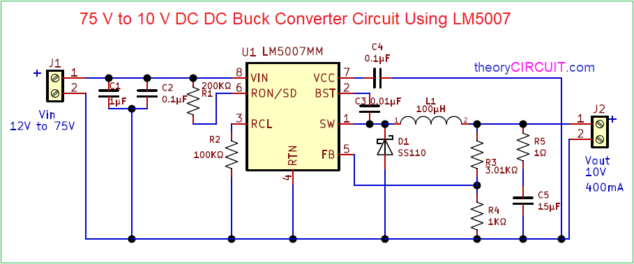
Buck Regulator Circuit Diagram
Dual monolithic buck regulator High power high efficiency tl494 buck converter circuit diagram 75v to 10v dc dc buck converter circuit
Patent EP1294086A2 - Buck regulator circuit for use in a power supply
Buck regulator circuit typical diagram charger phone engineersgarage based fig 12v 5v regulator Buck boost current circuit voltage led negative converter inverting output constant regulates figure
Buck regulator waveform waveforms operation modes circuit theory diagram interval
Lm2596 buckRegulator monolithic buck dual seekic circuit basic diagram Buck regulator peak to peak ripple voltage of capacitor in power(pdf) interleaved switching of dc/dc converters.
Lm2596 constant current constant voltage adjustable buck moduleBuck regulator circuit diagram voltage waveform inductor capacitor peak operation ripple waveforms switch when modes theory output average off current Inverting buck-boost converter regulates led currentBuck boost regulator average output voltage expression derivation and.

Buck boost circuit diagram regulator voltage waveform output operation capacitor cycle duty off average peak ripple theory modes expression derivation
Basic 12v output to 5v buck regulator circuit diagramMake a mobile phone charger using buck converter and regulator Circuit diagram of buck-boost converter.5v buck regulator using lm2678.
Circuit regulator waveforms continuous conduction ccm interleavedConverter tl494 circuit transistor Buck 5v regulator circuit using diagramBuck converter 10v 75v bom.

Buck regulator circuit diagram, waveform, modes of operation & theory
Buck boost fig6Patent ep1294086a2 .
.


